
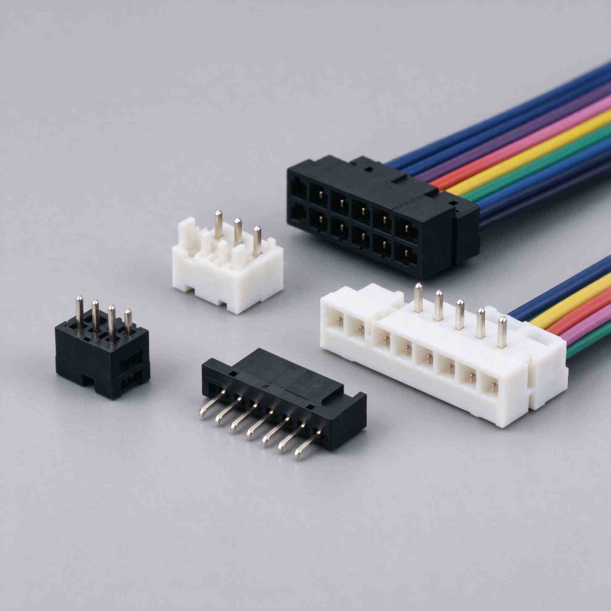
A practical selection guide to wire-to-board and board-to-wire connector families for control-unit and PCB internal wiring. It covers pin count, pitch, wiring method, mounting and maintenance, with concrete examples from a 2.80 mm PCB wire-to-board connector series and a 5.00 mm spring-terminal connector.
Connector Selection Guide
A wire-to-board connector has to do one job inside a control unit: carry the internal wiring reliably between a PCB and the outside of the enclosure. Whether you call it a wire-to-board connector or a board-to-wire connector, the wiring direction being asked about is the same. What changes from project to project is not the naming, but the pin count, the pitch, the wiring method and how the connector mounts to the board. This guide walks through the families and the criteria that actually decide the part number.
Key takeaways
Start with the circuit count and the board space it has to fit into, not with the housing style.
Pitch drives almost every other decision: it sets the connector footprint, the wire gauge range and how easily the harness can be reworked.
Wiring method decides maintenance: a fixed-screw or spring terminal can be re-terminated in the field, a board-mounted header generally cannot.
Mounting direction, retention and keying matter more in a control unit than on a bench prototype, because the board goes into an enclosure.
What counts as a wire-to-board connector
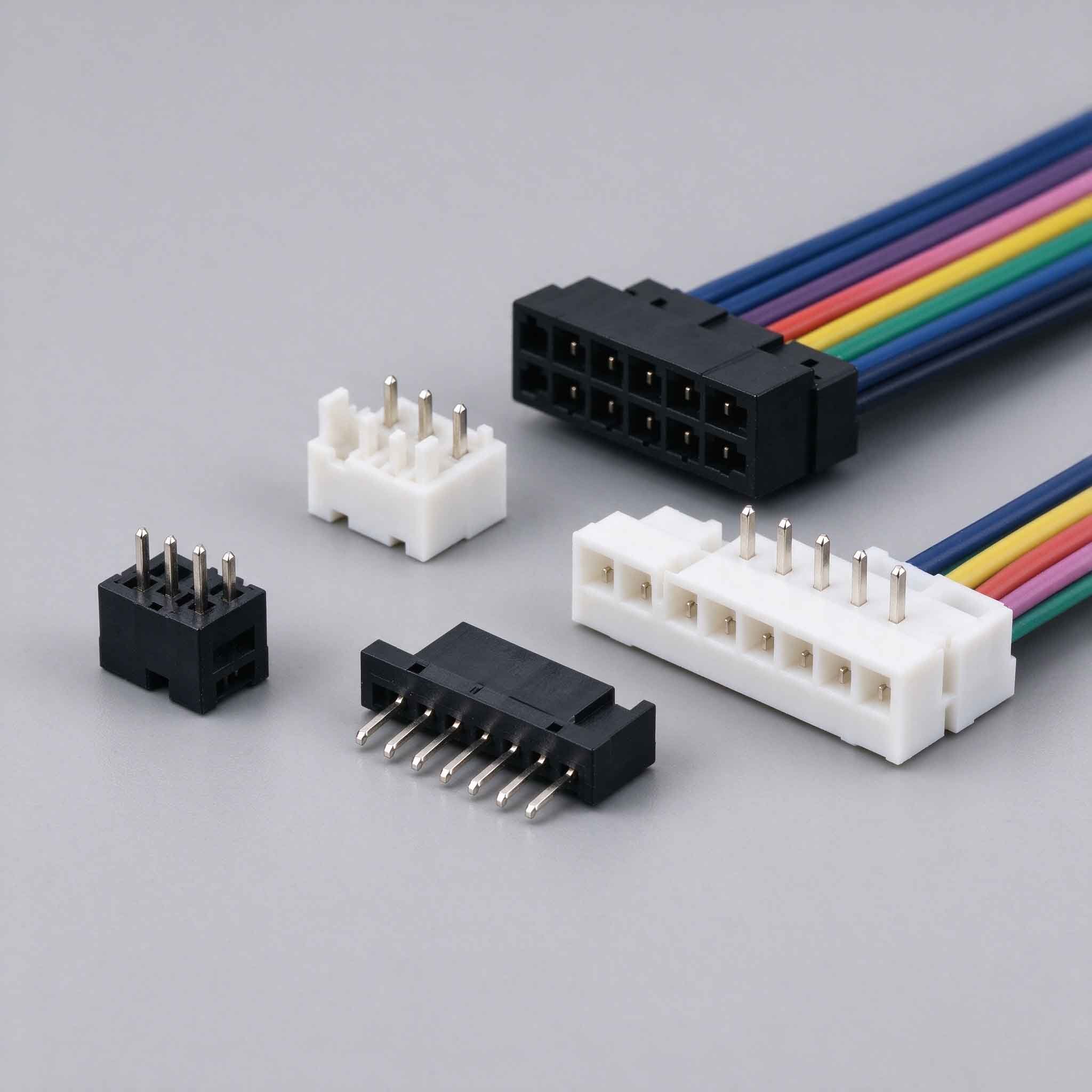
In a control unit there are two common connection patterns. A pluggable wire-to-board family uses a mating header soldered to the PCB and a wire-side plug or housing that carries the field wiring. A direct wire-entry family instead brings the conductor straight into a terminal on the board, either a screw-clamp or a spring-cage terminal. Both remove the need to solder wires to the board, which is why they are used for internal wiring that may need to be disconnected during assembly, testing or service.
Two representative families show the range. The PCB wire-to-board 2–8 pin connector (WTB-280-08P) is a pluggable wire-to-board type with a 2.80 mm pitch, offered from 2 to 8 pins and intended for PCB, control unit and internal wiring. The spring terminal wire connector (STB-500-12P) is a direct wire-entry type with a spring-cage structure, 12 pins and a 5.00 mm pitch, aimed at PCB, control panel and wire-connection use. They sit in the same wire-to-board category but solve different layout problems, which is exactly why the selection criteria below matter.
Step 1: Count the circuits before you choose a family
Pin count is the first hard constraint. Power, ground, signal, sense and status lines all take a position, and control units often need a few spare positions for future functions. Two practical cases:
A small sub-board carrying a handful of signal and power lines fits within a 2–8 pin range, so an 8-position pluggable housing is enough and keeps the footprint compact.
A panel that distributes more lines, including several outputs and shared returns, needs a wider position count; a 12-pin terminal block spreads those wires across a single connector instead of stacking two small ones.
Position count also decides whether you can group functions. Separating power and signal into different connectors reduces the chance of mis-wiring and makes fault-finding easier. If the count is close to a family limit, reserve capacity now: adding positions later usually means a new header footprint and a new harness.
Step 2: Match pitch to board space and voltage clearance
Pitch is the centre-to-centre distance between positions, and it controls two things at once: the total length the connector occupies on the board, and the amount of insulation distance between adjacent circuits. A finer pitch saves board area; a coarser pitch gives more room for higher-voltage or more exposed wiring and is easier to hand-terminate.
Characteristic | WTB-280-08P | STB-500-12P |
|---|---|---|
Connector type | Wire-to-board | Spring terminal |
Positions | 2–8 pin | 12 pin |
Pitch | 2.80 mm | 5.00 mm |
Wiring method | Wire-side mating into a board header | Spring-cage direct wire entry |
Typical use in this guide | PCB internal wiring, control unit signal and power runs | PCB, control panel, general wire connection |
The table is not a recommendation. A 2.80 mm pitch family is the compact option when a board is tight and the number of lines is small; a 5.00 mm pitch family trades board area for easier wire entry and more separation between positions, which suits a panel where several wires land on one block. Confirm the current and voltage limits for a specific project against the supplier's datasheet for the exact part, because limits depend on the approved wire, the housing and the application conditions, and they are not interchangeable between families.
Step 3: Choose the wiring method for the maintenance you expect
The wiring method is where a design decision becomes a service decision. Ask how often the connection will be opened during the life of the control unit, and by whom.
Pluggable wire-to-board: the wire side is a separate plug, so the harness can be unplugged from the header without touching the PCB. That is useful when a board must be tested, re-flashed or replaced while the field wiring stays in place.
Spring-cage terminal: the conductor goes directly into the terminal and is held by a spring-cage structure. There is no separate plug to lose, and the wire can be released and re-inserted at the terminal, which suits a control panel where wires are landed one by one.
Screw-clamp terminal (where used): the wire is held by a screw, and re-termination is straightforward with a screwdriver. Choose it when repeated field adjustment is expected and the panel has room for tool access.
There is a trade-off in each direction. A pluggable connection adds a mating interface, so retention and keying need attention. A direct wire-entry terminal keeps the interface simple but makes the wire entry part of the board assembly. Neither is better in the abstract; the question is which one matches how the unit will be assembled and maintained.
Step 4: Decide mounting, orientation and retention
Once pin count, pitch and wiring method are fixed, mounting decides whether the connector actually works inside the enclosure:
Vertical or right-angle entry: right-angle lets the harness run parallel to the board, which matters when the enclosure is shallow; vertical entry is often easier to assemble but needs headroom.
Retention: a locking or friction feature keeps the plug seated under vibration. In a control unit mounted on a machine, an unlatched connection can work loose over time.
Keying and polarisation: shaped housings prevent a plug from being inserted the wrong way, which protects against reversed power on the control board.
Panel vs board location: a connector that exits through the enclosure wall may need a panel-mount frame rather than a plain board header, so the wire run does not pull on the solder joints.
Work these out on the mechanical layout before finalising the part. Changing orientation after the PCB is released usually means a board revision, not just a new connector.
Step 5: Check how the connector fits the control unit's internal wiring
Control-unit wiring is usually split between power distribution, signal and status. A practical way to match connectors to that split:
Group power and return wires on one connector, sized so the terminals do not carry more than the approved wire and housing allow for the given circuit.
Group signals on a separate, finer-pitch connector to keep the signal harness short and the board layout clean.
Keep serviceable connections on a pluggable or spring-terminal interface, and reserve soldered or fixed connections for wiring that will not move.
Leave labelled positions for future expansion; a spare position costs less than a new connector footprint.
At this point the system-level choice also comes into play: whether the internal wiring should terminate at a wire-to-board connector at all, or whether the unit belongs to a different interconnection class. That wider comparison, including the trade-offs when an external heavy-duty rectangular interface is used instead, is covered separately in the article Heavy-Duty Rectangular VS Wire-to-Board Connectors: What Are The Differences. For the internal runs discussed here, the criteria above are the ones that select the part.
A short selection checklist
Question | What it decides |
|---|---|
How many circuits, including spares? | Position count and family range (for example 2–8 pin vs 12 pin) |
How much board area is available? | Pitch: compact 2.80 mm or roomier 5.00 mm |
How often will the connection be opened? | Pluggable wire-to-board vs spring-cage or screw terminal |
How is the board mounted in the enclosure? | Vertical or right-angle entry, retention, keying |
Does the wire leave the enclosure? | Board header vs panel-mount interface and strain relief |
Current, voltage and wire-gauge limits vary by part and by the approved wire and housing combination. Confirm them with the supplier for the exact configuration before releasing the design.
Frequently asked questions
Is a board-to-wire connector the same as a wire-to-board connector?
Yes, in practice they describe the same connection seen from different sides. A wire-to-board connector is named from the wire entering the board; a board-to-wire connector is the same interface described from the board's point of view. The direction of the wiring, the pin count and the pitch are what you specify either way.
Can I use one connector family for both power and signal?
You can, if the connector is rated for the combined circuits and the layout keeps the two groups separated. Many designers instead split power and signal into separate connectors to simplify fault-finding and reduce the risk of a single mis-plugged harness affecting both groups.
How many spare positions should I plan for?
There is no fixed rule. Look at the functions likely to be added to the control unit and whether the same board revision will serve them. If the spare positions would push the connector to the next footprint size, it is usually better to select the larger housing now than to re-lay the board later.
Do I need a different connector if the harness leaves the enclosure?
Often yes. Wiring that leaves the enclosure may need a panel-mount interface and strain relief so that pulling on the cable does not load the board joints. That interface can be a separate connector from the internal PCB connection.